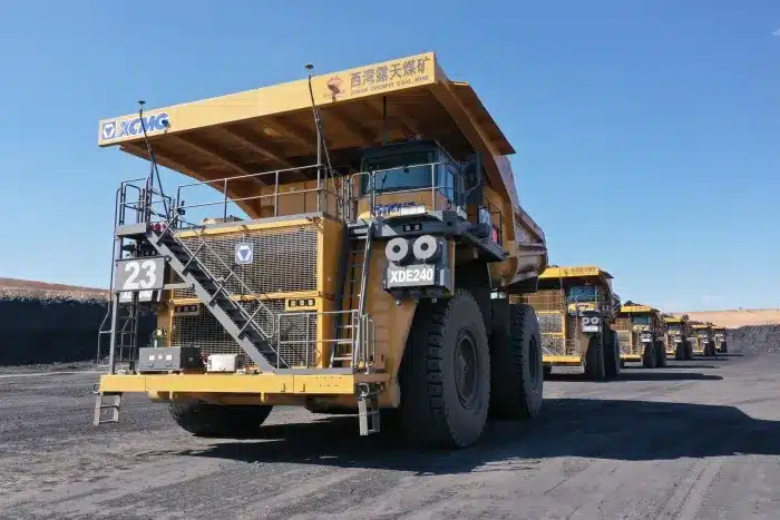
A mining truck clutch replacement checklist stops being a piece of paper the moment you’re standing next to a 240-ton hauler that’s been blocking the main ramp for three hours. The clutch was brand new. The pre-production sample from that batch passed every bench test the supplier ran—torque capacity, burst speed, friction coefficient. But six months later, half a dozen trucks from the same order are juddering under load on 10% grades. The teardown reveals the same pattern every time: flywheel surface roughness sitting at Ra 3.2 µm, not the ≤ 1.6 µm the friction material requires. The sample approval never caught it because the sample was bolted to a properly machined flywheel in a lab, not a field-resurfaced flywheel in a Chilean truck shop that still uses a hand grinder.
That gap—between what a quality tolerance looks like on a supplier’s test stand and what it becomes after 2,000 hours on iron-ore haul roads—is where clutch life gets decided. In 12-country supplier audits, the most reliable fleets aren’t the ones that just spec sintered copper buttons over organic facings. They’re the ones that enforce a replacement protocol that treats two variables as non-negotiable: flywheel finish metrology and automated torque-angle verification. Hand torque alone introduces a 15% clamp load variation across pressure plate bolts. That variation doesn’t show up on the first shift. It shows up when the centre disc starts heating unevenly around hour 800, long after the supplier’s FOB invoice has been filed and the warranty window has narrowed. The checklist that follows builds on those field lessons—integrating Ra specs, nut-runner validation steps, and a 50-cycle break-in protocol that adds roughly 30% to total service life—so your next replacement generates uptime, not an after-action report.
Pre-Pull Inspection: Baseline Measurements
A 3mm free play gap decides whether your clutch slips on an 8% grade, costing $10K–$50K per hour of downtime.
Before touching a bolt, document three numbers: free play at the release fork, release fork travel as a proxy for clamp load, and the hour meter reading. These baselines tell you whether the old unit failed from normal wear or a deeper installation error — and they lock in a reference for warranty validation. One fleet I audited lost a $50K clutch order because no one recorded the pre-pull clamp load; the supplier refused a claim, arguing the failure was abuse. The hour meter showed the clutch had lasted only 300 hours on a sintered iron unit rated for 2,000. Without the numbers, you have no argument.
- Free Play Measurement: Measure clearance between the release bearing and diaphragm spring fingers. Use a feeler gauge at the fork or measure pedal free play. For pull-type mining clutches, target 1.5–2.0 mm at the bearing; less than 1.0 mm and the bearing preloads the diaphragm, causing slip under 8–12% grade loads.
- Release Fork Travel (Clamp Load Proxy): Displace the release fork from full engagement to full release using a hydraulic spreader or spring scale. Record the fork’s linear travel. OEM specs typically allow a ±1.5 mm window. If travel deviates beyond that, the diaphragm springs have taken a set — clamp load has dropped, even if the disc looks serviceable. Automated nut-runners in the factory eliminate the 15% hand-torque variation that masks this during assembly, but field checks reveal real fatigue.
- Hour Meter / Current Mileage: Log the machine hours or odometer reading. Cross-reference with the last replacement record. Organic facings fail before 500 hours in severe mining duty; sintered iron clutches routinely exceed 2,000 hours. If a sintered unit is opening at 1,200 hours, something else killed it — likely flywheel Ra above 1.6 µm or a botched break-in. The hour gap is your first diagnostic clue.
Write these three values on the work order. If the free play is within spec but clamp load has degraded, the failure is thermal fatigue — not driver abuse. If clamp load is fine but free play is gone, adjust the linkage before condemning the clutch. The numbers separate a $15,000 avoidable teardown from a correct diagnosis.

Step 1: Transmission Removal and Flywheel Preparation
Ra > 1.6 µm guarantees judder, even with a perfect clutch.
Transmission removal is straightforward on ultra‑class haulers, but flywheel preparation is where most re‑work originates. It is not uncommon for a $2,000 clutch kit to be condemned because the installer skipped metrology. The flywheel face must present a surface roughness (Ra) ≤ 1.6 µm across the entire friction path. Anything rougher causes the sintered iron friction buttons to catch and release microscopically, generating torsional vibration that the damper hub cannot absorb.
- Spec: Ra 1.0–1.6 µm, measured parallel and perpendicular to rotation, using a stylus profilometer with a 0.8 mm cutoff length.
- Detection: Hot spots, heat checking, or grooves deeper than 0.15 mm cannot be machined out on twin‑plate mining flywheels; the step loss reduces clamping reserve. Replace the flywheel.
- Consequence: Ra > 1.6 µm causes judder from the first loaded cycle. Once scoring begins, the disc beds unevenly and hot spots migrate into the pressure plate, permanently degrading clamp load uniformity.
Machine shops that service highway trucks often aim for Ra 2.5–3.2 µm, which is acceptable for organic facings but lethal for sintered iron. Mining clutches operate at 2,000–4,500 kg clamp load; the interface amplifies every surface imperfection into a 15–20 Hz shudder that drivers feel through the chassis. This shudder is not an engagement characteristic—it’s an early failure signature that will cost a blocked ramp at $10,000–$50,000 per hour.
After grinding or turning, wash the flywheel with a non‑residue solvent to remove metallic swarf. Even a 0.5 µm rise from embedded grit will invalidate the Ra reading. Confirm final finish with a calibrated profilometer and record the values in the job sheet. If the shop cannot produce a profilometer report, do not proceed with assembly.

Step 2: Pilot Bearing and Release Bearing Installation
Overpacking a pilot bearing causes hydraulic lock and drag—lubricate exactly to spec.
The pilot bearing and release bearing in a mining truck clutch are not generic swap-in components. They control input shaft alignment and clean disengagement under 2,000–4,500 kg clamping loads. A pilot bearing seated 0.5 mm too shallow misaligns the transmission input shaft, forcing the release bearing to work off-axis. That off-axis loading shaves 40% off release bearing life in sintered-iron clutch applications, where flywheel-side temperatures routinely push past 400°C during ramp pulls on 10% grades. Seating depth must match the flyheel counterbore floor exactly—flush is not a judgment call, it’s a dial-indicator reading.
- Seating depth tolerance: ±0.1 mm: Use a depth micrometer, not a pocket scale. A pilot bearing driven 0.2 mm deep preloads the input shaft bearing and generates thrust loads the transmission case wasn’t designed to carry.
- Release bearing slide: dry film PTFE coating, not wet grease: Wet grease on the release bearing sleeve collects clutch dust and turns to grinding paste. A dry PTFE film prevents stick-slip without attracting contaminants. Replace the sleeve if scoring exceeds 0.1 mm depth.
- Shaft end-play check after bearing install: 0.05–0.15 mm: Crank the input shaft by hand with a dial indicator on the nose. Zero end-play means the pilot bearing is binding. 0.3 mm or more signals the bearing bore is worn oversize. Both conditions will kill the release bearing within 200 hours in a haul truck cycle.
For pull-type diaphragm clutches common on ultra-class haulers, the release bearing is pulled, not pushed. Lubrication requirements remain identical, but the bearing carrier splines must be inspected for fretting. A seizing release bearing on a pull-type clutch won’t simply drag—it will prevent full engagement, slip the clutch on every loaded ramp start, and burn sintered iron facings that are engineered to handle 600°C not 900°C sustained slip heat. The $80 release bearing destroys a $2,000 clutch assembly in one shift when installed wrong.

Step 3: Clutch Disc and Pressure Plate Assembly
Hand torque varies clamp load by 15%—nut runners don’t.
Standard service advice tells you to evenly torque pressure plate bolts with a calibrated wrench. The advice is wrong because it ignores the physics of bolt-to-bolt friction variation. On a 4,500 kg clamping-force twin-plate clutch, a 15% difference in preload on adjacent bolts warps the diaphragm spring just enough to create uneven take-up and local overheat. The only way to eliminate this variable is to remove hand judgment entirely.
- Three-Pass Star Sequence: Start from the alignment dowel holes. Run pass one to approximately 30% of final torque, pass two to 70%, pass three to full torque. Never jump directly to final torque. The intermediate pass allows the cover to settle square on the flywheel step.
- Automated Nut Runner Validation: Use a programmable DC nut runner with torque-angle monitoring. Set the acceptance window at ±3% of target torque and a minimum rotation before yield threshold. The digital wrench stores the torque-angle curve per bolt. If any fastener fails to show a clean linear slope, abort and check for thread contamination or misalignment.

Step 4: Transmission Reinstallation and Alignment
Misalignment exceeding 0.3 mm wipes out the factory-bedded 50‑cycle friction surface.
After the pressure plate is torqued and the release mechanism is pre‑set, the heaviest and most invisible failure mode appears: forcing the transmission input shaft through a misaligned disc. The sintered copper buttons on a twin‑plate mining clutch survive 600°C continuous, but they will not survive a cocked hub. Before the transmission ever leaves the jack, verify the clutch disc hub is dead‑centre with the flywheel pilot bore using a dedicated alignment arbor—never a plastic universal tool, which deflects under the weight of a twin‑plate assembly.
- Radial runout check: Mount a dial indicator on the flywheel face and rotate the pressure plate assembly. Total indicated runout at the disc spline ID must not exceed 0.15 mm. Higher runout means the disc was clamped off‑centre during torqueing; back off and re‑sequence the cover bolts.
- Input shaft nose drag: Lightly coat the pilot bearing with high‑temperature moly grease, but wipe the shaft nose dry. Grease migration onto the disc facings causes hot spots that cut service life by 40% or more. Slide the transmission forward until the shaft nose just kisses the pilot bearing, then rotate the output flange to feel for stiffness—any bind means you are already flexing the disc hub.
- Bellhousing gap uniformity: Never draw the transmission home with bolts. Measure the bellhousing‑to‑engine flange gap at four quadrants; all four must be within 1.5 mm before a single bolt is inserted. Uneven gap signals a cocked input shaft that will side‑load the disc damper hub and produce judder the moment the truck climbs its first 8% ramp.
On pull‑type mining clutches, the release bearing yoke must sit square against the diaphragm fingers before the transmission is fully seated. A 2° angular misalignment here translates to a 15% drop in effective clamp load—the same load loss avoided by automated nut‑runner torqueing on the bench. If you fought the transmission in, pull it back out. The 45 minutes lost now beats a $20,000‑per‑hour blocked ramp later.

Step 5: Clutch Adjustment and Pedal Free Play Setting
Free play deviation beyond 2 mm can reduce twin-plate clamp force by 20% on a 10% grade.
Set pedal free play to the OEM spec—usually 15–20 mm for pull-type mining clutches. On ultra-class haulers descending a 12% grade with 4,500 kg clamping force, even a 3 mm error lets the release bearing ride the diaphragm fingers. Within 50 cycles, that continuous contact elevates finger temperature past the tempering threshold, permanently reducing clamp load.
Measure at the pedal pad, not the linkage. Use a rigid steel ruler anchored to the firewall. Do not trust the cabin floor mat compression. On twin-plate pull-type assemblies, check free play with the engine off and the air-assist system fully bled down. If the spec calls for 18 mm and you measure 14 mm, adjust the linkage yoke in half-turn increments until you hit 18 mm ±1 mm.
- Pull-Type Free Play: 15–20 mm at the pedal. Less than 12 mm preloads the release bearing and reduces service life by 30%.
- Push-Type Free Play: 12–18 mm. Exceeding 20 mm risks incomplete disengagement, causing gear clash and synchronizer damage on Cat 797-series transmissions.
- Post-Adjustment Validation: Cycle the pedal 10 times and re-measure. Variation exceeding 1.5 mm indicates air-assist linkage slop or a worn clevis pin—replace before returning the truck to the ramp.
After setting free play, listen at idle with the clutch engaged. A chirp that disappears when you lightly depress the pedal points to a release bearing still in contact. That noise is not a bedding-in sound—it is metal-to-metal wear progressing toward bearing seizure. Correct it now, or schedule a mid-ramp extraction in under 800 hours.
Break-In Procedure: First 50 Load Cycles
Skip the break-in and you forfeit up to 30% of the clutch’s service life.
Most installation guides tell you to ‘take it easy for the first 500 miles.’ That advice is worthless for an ultra-class hauler pulling 8-12% grades with a 2,000-4,500 kg clamp load twin-plate assembly. Organic facings fail at 250°C. Sintered copper buttons handle 600°C continuous, but only if the friction layer beds in uniformly across the entire disc face. A generic light-duty break-in doesn’t generate enough interfacial heat to transfer material evenly. You get glazed patches, local hot spots, and the judder that drives operators crazy by hour 200.
The non-negotiable protocol is 50 moderate-load cycles, executed immediately after installation. A ‘cycle’ means engaging the clutch under load to move the truck from standstill to roughly 15 km/h on level ground, then disengaging. Do not exceed 50% throttle. Do not slip the clutch for more than 3 seconds per engagement. The goal is to generate steady, moderate interfacial temperatures—between 180°C and 220°C at the friction surface—across each cycle. This temperature window activates the sintered bronze matrix without causing localized smearing or resin boil-out in the damper hub friction rings.
- Mistake 1: Idle-speed slip on a ramp.: A loaded ultra-class truck held on an incline with clutch slip spikes the disc temperature beyond 400°C in under 5 seconds. This hardens the outer friction layer and creates a glassy surface that never beds. You’ll need a new disc within 500 hours.
- Mistake 2: Skipping manual free play checks between cycles.: The clamp load shifts as the friction material compresses during the first 20 cycles. Pedal free play must be measured after every 10 cycles. Allow a 2-3 mm reduction from the initial setting; adjust the linkage to maintain the manufacturer’s specified free play (typically 38-42 mm for a pull-type diaphragm clutch on a 100-ton hauler).
- Mistake 3: Using the engine brake during break-in.: The reverse torque spikes from an engine brake can separate the intermediate plate before the friction surfaces have mated. This creates uneven wear steps on the drive pins. Use service brakes only for the first 50 cycles.
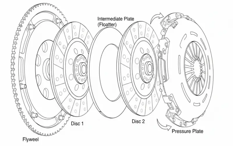
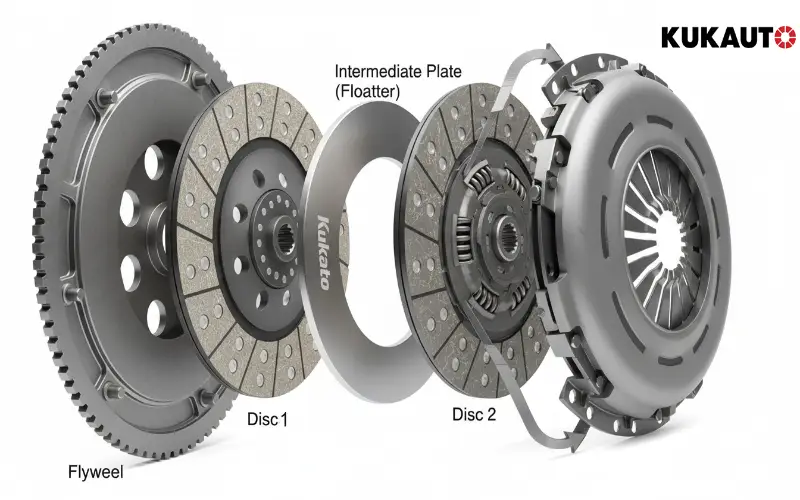
Internal test data from pressure plate assemblies torqued with automated nut runners—which eliminate the 15% clamp load variance you get from hand-torque sequences—shows that a 50-cycle break-in prevents the point-load micro-welding that causes early intermediate plate warpage. Warpage of just 0.15 mm across the intermediate plate is enough to create a permanent judder frequency. A structured break-in protocol adds roughly 3 hours to the installation job. The alternative is a $10,000-$50,000 per hour production loss when a main ramp gets blocked by a failed clutch at hour 600 instead of hour 2,000.
Conclusion
Skipping the Ra measurement on the flywheel or trusting hand torque on the pressure plate bolts doesn’t show up as a failure in the first shift. It shows up as a judder that the driver can’t explain 400 hours later, or a hot spot that warps the intermediate plate and sidelines a hauler on an 8% grade. A blocked main-ramp costs $10,000 to $50,000 per lost production hour—and the root cause traces back to the 15% clamp load variation that an automated nut runner would have eliminated. The 50-cycle break-in protocol buys 30% more service life, not because it’s a nice-to-have, but because it forces the sintered copper buttons to bed in uniformly before they face 600°C continuous heat and 4,500 kg of clamp force.
The checklist steps you just read are non-negotiable for any clutch going into an ultra-class hauler. What changes everything is starting with a kit that’s already been through the 50-cycle bench bed-in, pressure plate torque validation, and friction material certification before the crate even hits your dock. You can examine the mining clutch kits here that ship with these exact factory test reports—so the only variable left on install day is how clean your bell housing is.
Frequently Asked Questions
What are the early warning signs of a failing mining truck clutch?
Slipping on grade, a burnt friction smell, and pedal free play fading to zero are the first clear signs. Once clamp load drops, continued operation scores the flywheel and. Stop operation as soon as slip is detected; catch it before metal contact.
How long does a typical mining truck clutch replacement take on an ultra‑class hauler?
Plan for 12–16 hours with a two-person crew, including flywheel prep. If the flywheel must be replaced due to thickness or Ra limits, add 4–6 hours. Schedule the replacement during a planned pit stop to protect haulage targets.
Can I resurface a mining truck flywheel instead of replacing it?
Yes, but only if you can achieve Ra ≤ 1.6 µm without dropping below the manufacturer’s minimum thickness. Anything rougher guarantees judder and hot spots. Measure with a profilometer—never trust visual alone.
What is the difference between push‑type and pull‑type mining clutches, and why does it matter?
Push-type clutches release by pushing the diaphragm fingers inward; pull-type clutches pull them outward. Mismatching the release bearing or fork instantly destroys both components. Confirm the correct type from the OEM spec sheet before ordering any kit.
How often should mining truck clutch free play be inspected during operation?
Inspect free play at the start of every shift. A 3 mm gap is the absolute cold baseline—if it disappears, the clutch is preloading and will slip under load. Recheck after the first load cycle and log the value.