
Introduction: The Unsung Hero of the Clutch System
When a heavy-duty truck struggles to climb a grade, the first instinct is often to blame the friction disc. “The facing is worn,” they say. But in many cases, the friction material is fine. The failure lies in the invisible force that holds that material against the flywheel: the Clamping Load.
Defining the Pressure Plate’s Job
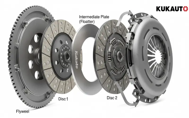
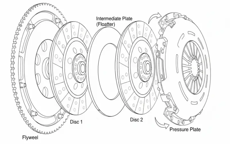
The pressure plate (or cover assembly) is not just a housing; it is essentially a giant, high-tension spring. Its sole purpose is to exert thousands of Newtons of force to lock the transmission input shaft to the engine crankshaft.
Torque Capacity (T) = μ × R × Clamp Load
Where μ is friction coefficient, and R is the mean radius. This formula proves that even the best ceramic buttons (high μ) will slip instantly if the Clamp Load is insufficient.
The Consequence
What happens when clamping load drops by even 10%? Immediate slippage under peak torque. This slippage generates immense heat, which further weakens the spring steel, creating a vicious cycle of failure known as “Thermal Fade.”
Deep Dive: What is Clamping Load?

The Source of Force: Coil vs. Diaphragm
Coil Springs (Old Tech): Used in older tractors. They follow Hooke’s Law—as the clutch disc wears and gets thinner, the springs extend, and clamping force drops linearly.
Diaphragm Springs (Modern Standard): Used in almost all modern trucks. This conical steel disc offers a unique advantage: Non-Linear Characteristics.
“The magic of the Diaphragm Spring is its geometry. Unlike a coil spring that loses force as it extends, a diaphragm spring can actually maintain or even slightly increase its clamping load as the friction disc wears thin. This ensures that a clutch with 50% wear holds just as much torque as a brand-new one. This is the core advantage of modern pressure plates.”
The Load Curve & Hysteresis
Every pressure plate has a unique “fingerprint” called the Hysteresis Loop. This curve maps the force required to release the clutch versus the clamping force it exerts. A high-quality plate has a smooth curve; a poor-quality plate shows jagged spikes due to internal friction.
Thermal Fade
Cheap pressure plates work fine when cold. But at 200°C (common in stop-and-go traffic), inferior steel “relaxes.” The spring rate drops, clamping force vanishes, and the truck is stranded. This is why metallurgy matters.
Torsional & Lift Characteristics: The “Feel” of the Clutch
While Clamp Load determines if the truck moves, Lift Characteristics determine if the truck can shift.

Pressure Plate Lift (Release)
“Clean Separation” is critical. When you press the pedal, the pressure plate must pull back evenly and sufficiently (typically 2-3mm) to free the disc. If the plate lifts unevenly (wobbles), the clutch drags, destroying the transmission synchronizers.
Drive Straps (Leaf Springs): The Unsung Heroes
Look at the side of a pressure plate. You will see sets of thin steel strips connecting the cover to the iron plate. These are the Drive Straps.
Function: They transmit the engine’s torque from the cover to the friction surface while allowing the plate to move axially (in and out).
Failure Mode: In cheap clutches, these straps are brittle. One hard launch, and they snap. When they break, the pressure plate stops spinning, and you lose all drive. Kukauto uses multi-layer, high-tensile spring steel straps to withstand shock loads.
The “Soft Pedal” Paradox
How does Kukauto achieve massive clamping load (e.g., 12,000N) without making the pedal impossible to press? We optimize the Leverage Ratio of the diaphragm fingers. By precisely calculating the fulcrum point, we multiply the driver’s foot pressure, delivering high clamp load with a comfortable pedal feel.
The Manufacturing Secret: Heat Treatment & Material Science
You cannot see quality with the naked eye. A $50 pressure plate looks identical to a $150 one. The difference is in the molecular structure.
51CrV4 Steel
We strictly use 51CrV4 (Chrome Vanadium) spring steel for our diaphragms. This alloy offers exceptional fatigue resistance and thermal stability. Unlike standard carbon steel, it maintains its spring rate even after thousands of heat cycles.
Heat Treatment Process
Forming the spring is easy; locking in its memory is hard. We use a precise Austempering process followed by shot peening. Shot peening bombards the surface with steel beads, compressing the outer layer and significantly increasing resistance to fatigue cracks.
Testing Protocol
Every single Kukauto pressure plate unit undergoes a “Load Test” before packaging. We verify:
- Clamp Load: Must meet OEM spec (e.g., 12,000N ±5%).
- Release Load: Ensuring the pedal effort is within spec.
- Lift: Ensuring the plate retracts fully and evenly.
Troubleshooting: Signs of Pressure Plate Failure
| Symptom | Physics Behind It | Probable Cause |
|---|---|---|
| Slippage | Insufficient Clamp Load | Worn diaphragm spring, heat fade, or incorrect adjustment. |
| Hard Shifting | Poor Lift Characteristics | Plate not pulling back far enough (Drag), broken drive strap. |
| Vibration / Judder | Uneven Clamp Load | Diaphragm fingers not level, causing the plate to tilt engaging. |
Sourcing Guide: How to Validate Manufacturer Claims
How do you know if a supplier is selling you high-quality engineering or just shiny scrap metal?
📊 Ask for the Load/Deflection Curve
This is the ultimate lie detector. A professional manufacturer can provide a graph showing the force vs. travel for their pressure plate. If a supplier cannot provide this curve, they are likely just an assembler, not a manufacturer.
Checking “Finger Height” Consistency
Visually inspect the diaphragm fingers. They should be perfectly level. If one finger is higher than the others, the release bearing will wobble, causing vibration and premature bearing failure.
Avoid “Rebuilt” Pressure Plates
In heavy-duty applications, rebuilt plates are a gamble. You cannot “un-fatigue” metal. A sandblasted cover might look new, but the spring steel inside has already endured millions of cycles. For fleets, the cost of downtime far outweighs the savings of a rebuilt unit.
FAQ: Technical Questions
Conclusion
The pressure plate is the muscle of the drivetrain. Understanding the physics of Clamp Load, Non-linear Spring Characteristics, and Lift Geometry empowers buyers to make better decisions. Quality is not just in the finish; it is in the metallurgy and the testing data.
Don’t leave your fleet’s uptime to chance. Choose pressure plates backed by data, science, and rigorous testing.
Experience Lab-Tested Consistency
Equip your fleet with Kukauto’s premium pressure plates. Engineered with 51CrV4 steel and validated with individual Load/Deflection curves for guaranteed grip.